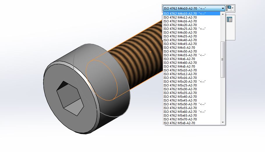
The fasteners library, often referred to as the Toolbox in the CAD world, is one of those simple things in CAD systems that needs to be managed by the engineering team. In reality, this “simple” tool turns out to be not so simple at all and there are consequences for the entire company when its importance has been underestimated. This article will give you some background information, and lists a few different approaches and options you have when trying to optimize it.
What is the Toolbox?
The Toolbox, especially in the SOLIDWORKS world, refers either to the built-in Toolbox by SOLIDWORKS or to a manually created library when using Excel-based configurations.
The Toolbox is one part of a standard components library, which is mainly focused on fasteners and other standard components. Generally, it includes all the fasteners that are fully standardized and can be purchased from any supplier. It also includes other elements such as bearings, structural members, sprockets, etc, which have become de facto standard due to big suppliers like SKF, Unistrut and so on. However, these elements tend to be quite limited and as a result, they’re not included in the built-in Toolbox and are configuration based. This article focuses more on the fasteners instead of those items.
How Toolbox Components are Handled in ERP Systems?
There are different approaches when it comes to managing fasteners in ERP systems. Usually, this depends on company profile and how the production is organized.
When the production is “in house” and the processes are long and stable, then you can typically find the fasteners on a shelf, and stock department ensures that the shelves are full. This also results in a paradigm where it’s impossible to keep all the fasteners in production; thus limitations in the design library are needed.
When the production is project-based and no-one knows, what is needed in the next project, then the fasteners will be ordered according to the BOM.
When the projects are outsourced, then generally speaking, the engineering team does not care about it at all. However, fasteners must be shown in a clear way in the BOM.
Toolbox Components Variants Reduction
Reducing the amount of Toolbox components in the design library is a crucial task, especially in “in house” production. This smoothes the process and reduces necessary stock sizes. There is an increasing global trend to hire workers either part-time or as rented workforce, but these people don’t have the same skillset that an experienced specialist has. A smaller amount of different fasteners makes life more comfortable for them as well.
The things to keep in mind when reducing the amount of fasteners are as follows:
Reduce fastener types used
Reduce different diameters and lengths available
Reduce grades and surface finishes available
Giving less options to choose from leads to simpler plans and as a result, to less mistakes from the workers. There is a tendency to pull required (often different) fasteners from the shelves and bring them to the assembly table all at once. Then during assembly the longer bolts are used first without much attention being paid to which lengths should be used and this leads to the shorter ones being used last and sometimes in places where longer bolts were needed.
This situation may become extremely dangerous when only one side of the bolt is visible for inspection, because quality control won’t be able to tell the difference and it will go unnoticed until something bad happens. These results, however, are something no one wants to see.
Joint vs. Process Excellence
During the design process, every joint is designed to be perfect. This means that the suitable diameter and the best length are chosen.
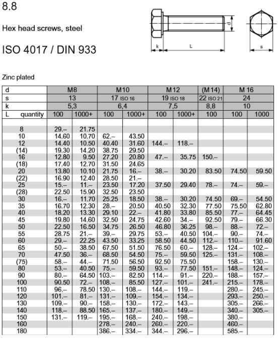
Here is an example of a common bolt ISO4017 (DIN933):
For example, if an M10 bolt is taken, then the length increments are between 2 and 5 mm, depending on the length.
As a result, engineers are ordered to use “optimal” lengths. Unfortunately, perfect engineering does not exist and this kind of approach can result in a disaster on the shop floor. Furthermore, it’s hard for a worker do differentiate between an M8, an L8 and an L10. Are those 2mm-s really that important? Instead just use the bolts with a 10mm length.
With this in mind, a question arises, whether CAD libraries and Toolboxes used in a company help to limit nomenclature? We firmly believe that limiting possible choices leads to the engineering team spending less time choosing fasteners and the assembly team spending less time on production. It’s a Win-Win for everybody.
Practical CAD Management Approach to Limiting Fasteners
By default, all fasteners from all the standards are available in Toolboxes and it’s smart to not fully block non-preferred choices. There may be a need for them in some cases. However, the right approach depends on how co-operative the engineering team is and how the Toolbox is set up. I’ll discuss some typical cases and give some proposals in the following chapters.
We strongly recommend having a company standard in which only the preferred fasteners should be available. Problems start to arise in cases when a fastener needs to be used that isn’t handled in that standard.
Preferred Lengths are Marked
A method that doesn’t limit you is to simply mark the preferred fastener configurations with an arrow, such as “<–” in the end of the configuration description.
It’s a simple thing that helps the engineers to choose a preferred fastener and at same time retains the flexibility for choosing something else if the situation calls for it.
It’s not recommended to change the configuration name itself because when it’s changed (preferred fasteners can change over time) the old assemblies will have problems due to the referred configuration name not existing anymore.
In an Excel based “Toolbox” it’s easy to add a configuration description, but unfortunately this does not apply to the Toolbox built into SOLIDWORKS. Currently an easy way to somehow mark configurations doesn’t exist, which makes this complicated to use in practical work.
If someone can recommend a way for a meaningful workaround (especially for single configuration components) then we’d love to hear about it in the comments below! Currently there’s the option for manually making changes later, but this is not the way how the Toolbox is meant to be used.
 In Conclusion
The topic of fasteners may seem simple at first glance, but in real life, it’s full of things to think about and only a team working together can prevent these kinds of issues before they escalate and start to have a serious effect on other departments within the company as well.
How are things and standards organized in your company? Let us know! We’re always looking forward to reading your thoughts and tips in the comment section below.
If you’d like to read more about this topic and how to set up a custom Library or a Toolbox then pick up our CAD Administration Handbook for SOLIDWORKS where these topics are covered in more depth.
Links:
Discussion about SOLIDWORKS’ Toolbox:
https://forum.solidworks.com/thread/81993
A world famous novel about production and local optimization:
The Goal: A Business Graphic Novel, Eliyahu M. Goldratt

Great topic 🙂
However, SWx has a well developed toolbox. Can you say the same about so-called top design softwares, Catia and NX?
Hi,
Unfortunately, we do not have too much experience with Catia or NX. About SW Toolbox, It is a great tool, but we would argue that it could be so much better. Right now it needs a lot of configuring to be done to get it work properly.
Hi,
I’m pretty sure (actually I wan to believe) that Catia and NX have similar tools. Engineering problems and design methods are similar and not depends so much from CAD system. Another topic is how easy is to implement and get this standard parts system efficiently work.
I would say that SolidWorks toolbox has lot of issues, however this is relatively simple nad there are tons of information how to get this work in proper way (read: how to use acceptable workarounds :).
I never use Toolbox, a real pain in the neck. If your Toolbox set up is different from your providers or vendors Toolbox, you have a mess on your hands. Another reason not to use it, is that the fasteners used on the shop floor probably have different critical dimensions vs. the Toolbox files. Best practice is to measure the hardware in the shop, and just make your own hardware Part files. BTW, SOLIDWORKS has known all about these Toolbox problems, and does not plan to fix them at all.
For hardware size or „dimensions errors“. I would not put all the blame to SOLIDWORKS.
I would look more at how fasteners are produced:
For example, when a producer is in Asia and delivering to all over the world. In such a case typically DIN, ISO, EN, ASTM, ANSI, GB, GOST, etc. standards must be considered. There are obviously available conversion tables, but there are cases when real measures are different in a standard, but conversion table tells that fasteners are equivalent. Quite often, standards are not properly reviewed and verified, what is written there.
One more variable may be a salesperson, who promises something which is not available or not possible to produce.
In short, this is how items in your local hardware store are different from 3D model.