Mirroring and symmetry are like some sort of an ancient code that is visible everywhere in the world. Most living creatures are somewhat symmetric. This also holds true in the technical world, where objects have a tendency to be symmetrical. There are many places in even simple design that need symmetry -for example using both left and right-hand components. Due to this, the first reaction may be that this is going to be easy and let’s get to it, but since we’re working in a not-so-perfect CAD-PDM world, it’s best to be prepared and to build a common understanding of how these things are handled.
Since this is going to be a long subject, it will be divided into three separate articles.
- 1/3 – Making a mirrored part directly from the original part (without using assembly features)
- 2/3 – Making mirrored parts in an assembly
- 3/3 – Making mirrored assemblies in an assembly
Parts two and three will be published shortly.
In General
What is considered to be symmetric in design?
There are many different types of symmetry in mechanical engineering, but let’s look at this from a SOLIDWORKS’ modelling point of view. There are the following options:
- Symmetric regular part
- Symmetric sheet metal part
- Weldment multibody part
- Weldment single body part
- Symmetric assembly
All of the elements listed have different approaches as to how the design data is managed. However, one should assume that symmetrical components are generally changed together. Furthermore, the consumption of both left- and right-handed parts is generally the same. Without these requirements being fulfilled, there’s little point in talking about symmetry in the components at all.
Identifying Symmetric Components
One of the key topics with symmetrical design is how to create their IDNumbers. Most numbering strategies depend on the company’s chosen design method. However, do not forget that users should somehow know that a mirrored version also exists. Therefore, in addition to the number, there should also be some text string in the descriptive field to notify the user of exactly that.
Numbering Strategies Without PDM
Without a data management system two basic strategies remain. In a single configuration environment the mirrored version is given the suffix “M”. When using a multi-configuration strategy, it’s smart to add the second configuration and the suffix “M” to end of the configuration name. R and L can be used to identify left- and right-handed versions.
Single configuration approach
| File name | Config. name | IDNumber Property | Description | Drawing file name |
|---|---|---|---|---|
| CadA-P000721 | "Default" | CadA-P000721 | Bracket - R | CadA-P000721 |
| CadA-P000721M | "Default" | CadA-P000721M | Bracket - L | CadA-P000721M |
Multi-configuration approach
| File name | Config. name | IDNumber Property | Description | Drawing file name |
|---|---|---|---|---|
| CadA-P002656 | 01 | CadA-P002656-01 | Bracket - R | CadA-P002656-01 |
| CadA-P002656 | 01M | CadA-P002656-01M | Bracket - L | CadA-P002656-01M |
| CadA-P002656 | 02 | CadA-P002656-02 | Bracket 2 - R | CadA-P002656-02 |
| CadA-P002656 | 02M | CadA-P002656-0M | Bracket 2 - L | CadA-P002656-02M |
With a PDM System
One would think, that when using PDM, it would be better to just give the next serial with PDM. Unfortunately, this is not so.
PDM is only able to give serials to mirrored parts in a limited way. How to do that, is covered in this article. However, when using the mirror feature in an assembly, as described in parts 2 and 3, PDM is not able to give serials to those mirrored parts and assemblies. This is once again an example of how the engineers in the PDM department haven’t communicated with the SOLIDWORKS’ features department or vice versa. This basically results in a situation where one should approach mirroring as if they didn’t have the PDM at all and just adding an “M” to the IDNumber. The major drawback of this is when the need for a copy tree arises. This will mean a lot of manual work where mirrored items need to be renamed or PDM will give the mirrored parts separate serials as well.
This may seem illogical, and it is, but as long as PDM is unable to give serials to parts and assemblies created with the opposite hand mirror feature from the assembly, there is no clear and simple way to go about doing this.
A Decision to be Made
How these things are approached within the company must be decided together with the lead engineers and by the CAD administrator. Clear manuals and procedures must be made and explained to the other engineers and to the users. It must be stressed that these procedures should never be avoided, for it is the only wat towards healthy data management. and they should never be avoided. This is the only way towards healthy data management. Allowing deviations from the rules will result in a data management nightmare sooner than one would usually expect.
Creating a Mirrored Part Directly from the Original Part
Modelling strategies also depend on whether and how the configurations are used. It’s important to always use the same method and it will be a huge step ahead when all the engineers in the company or the team will have the same understanding of this and the same approaches. That being said, the most stable and therefore the recommended stategy is to use singe configuration parts.
To create a mirrored part directly from the original part, use the following steps:
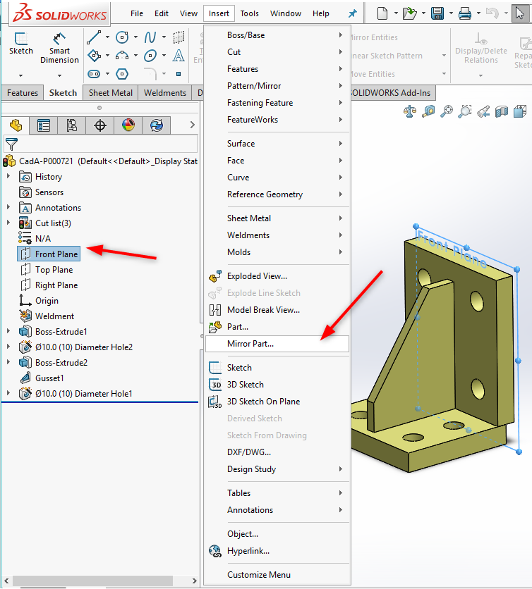
Select Plane and then Insert -> Mirror Part. (“Mirror Part…” is greyed out if a plane is not selected)
 2
2
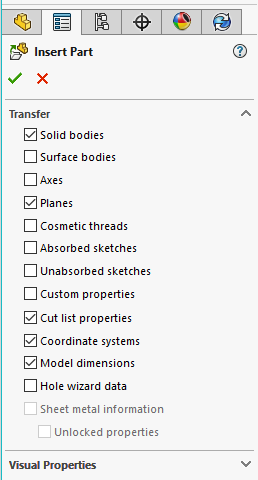
When weldments are used, select the “Cut list properties” to be populated in the “Cut list properties” of the new part. When creating mirrors from sheet metal parts, use the checkboxes accordingly. You may notice that the neat feature of “Unlocked properties” is only available for sheet metal parts. This is another strange thing within mirroring, as this should be available for both “Custom properties” and “Cut list properties” as well.
Now, it becomes possible to save the mirrored part as one would save a typical part with a unique serial given by PDM. This is the only approach that allows the PDM to give a mirrored part a serial number easily.
In any case, refer to the previous chapter “Numbering Strategies” and name the fields accordingly.
Remember that the mirrored part updates automatically only when the mother (referenced) part is opened!
When using a Configuration Strategy
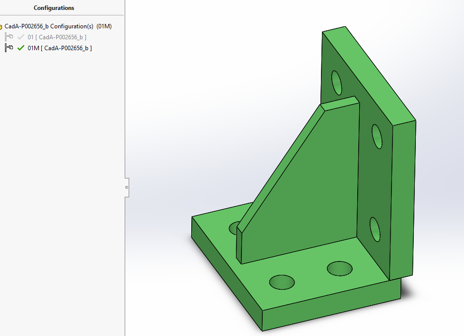
If there is a need for a configuration based mirror without creating it inside the assembly, the approach is similar to the previous example. To make a configuration based mirror of the “yellow bracket” use the approach indicated below.
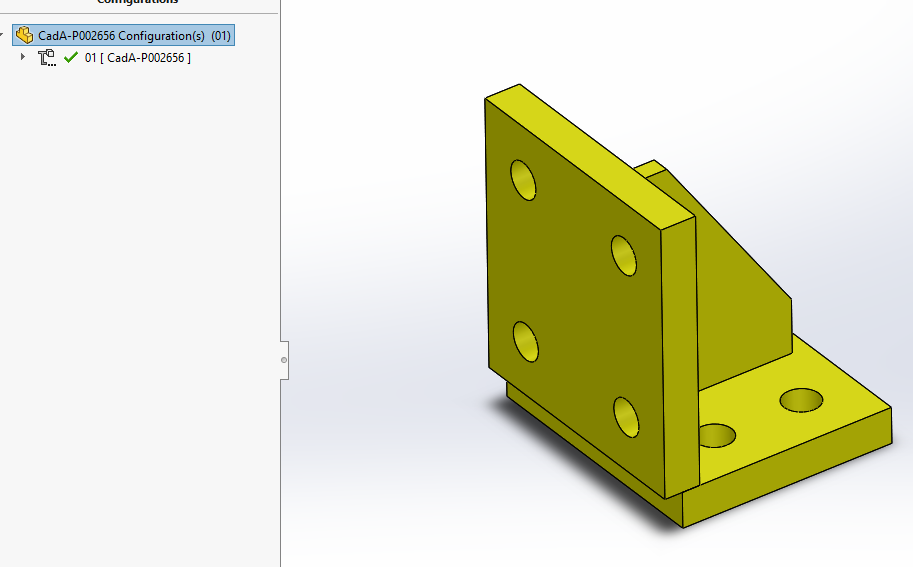
Use the “Part mirror” feature to make an opposite mirrored version of the detail or weldment.
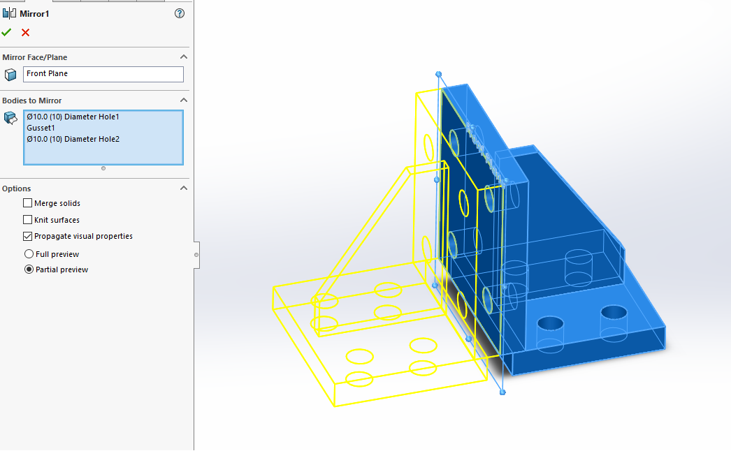
And then use the “Delete/Keep Body” feature to delete bodies of the original side.
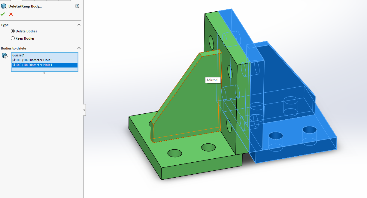
Then simply add the second configuration with the suffix.
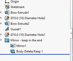
It is advised to put mirrored features in a single folder named “Mirror – keep in the end” (of the feature tree). These features must always remain in the end of the feature tree. Keep in mind that when Adding/Deleting bodies, the “Mirror” and the “Delete/Keep” features must be manually updated accordingly.
Go back to the default configuration to suppress the “Mirror” features.
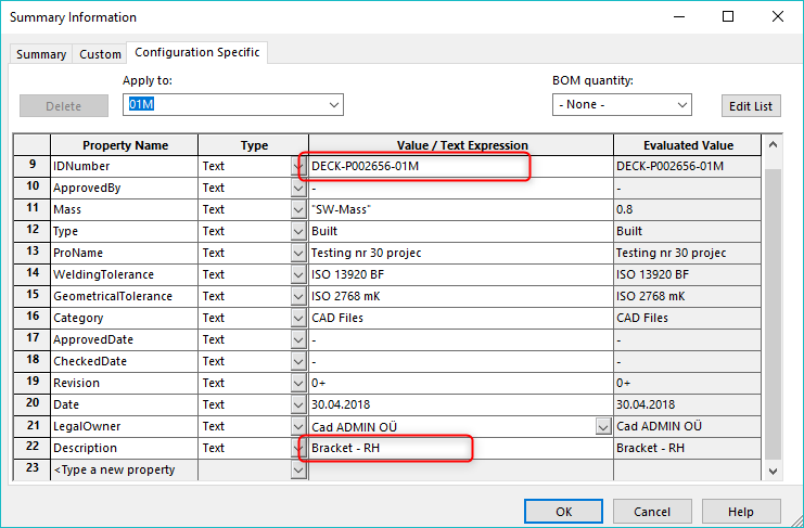
Also, check that the meta-data is filled properly for the derived configuration.
Now, when inserting the bracket to an assembly, it will be possible to choose which configuration will be used, the “Default” or the “Default_M”
A multi-configuration approach within PDM is often a much better approach since there is less hassle with serial numbers should a tree be copied. The file names for the mirrored drawings must still be manually altered, but it’s rather easy to filter them out in such a case.
The next parts will be published shortly. In the meantime, be sure to subscribe and we’ll keep you posted!
Hi Alar,
how about fromparent+ function to call properties from the original part to the mirror version?
We use it often, but sometimes SW just does not want to accept it. I keep filling it in with no luck… do you have any experience with this?
Thanks,
Barbara
Hi Barbara,
fromparent+ has created headaches for us as well. The fact it sometimes writes “fromparent+” in front is especially annoying. It now depends what is the need but we believe, that because of data management issues, at least ID Number and Description should be different for mirror part, thus import custom properties from parent part should be disabled. Have seen that in 2018 it should be possible to choose what will be linked and what not, but currently have no experience with it. Big problem is that Mirroring is a nice feature, but does not work well with PDM system.
Ok, thank you. We will see in 2018 if anything will be better 🙂