This is the second part in the series of articles on symmetry and mirroring in SOLIDWORKS, therefore it’s recommended to read Part One first.
Symmetry in assembly works as similar and is just as essential as it is with parts. Still, there are things that you should know to be more productive and to use the software in a more meaningful manner.
This is the second part of 3 part post about mirroring in SOLIDWORKS with the use of the PDM system.
See other parts here:
- 1/3 – Making a mirrored part directly from the original part (without using assembly features)
- 2/3 – Making mirrored parts in an assembly
- 3/3 – Making mirrored assemblies in an assembly
Simple mirroring
We hope that your models are built around planes kept in the logical center of geometry. This is something that should be obvious, but is an often forgotten principle. All the following examples assume that there is no need to add special mirror planes. They will however cover creating a mirrored side in a SOLIDWORKS model.
NB! Always check, that the parts to be mirrored are resolved!

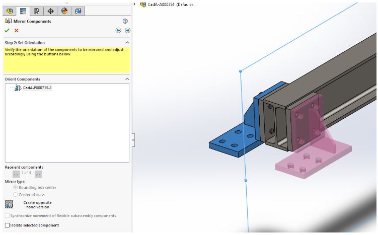
“Reorient components” gives you the ability to rotate components should the need arise. However, do consider that it can be dangerous as SW will occasionally orient parts in an illogical way during initial mirroring or even worse – forget the correct orientation altogether.
In this example, the part and the fasteners are mirrored with same Feature order. In larger designs, it would be best to mirror the fasteners separately to give better control when “Simplified” configurations are required!
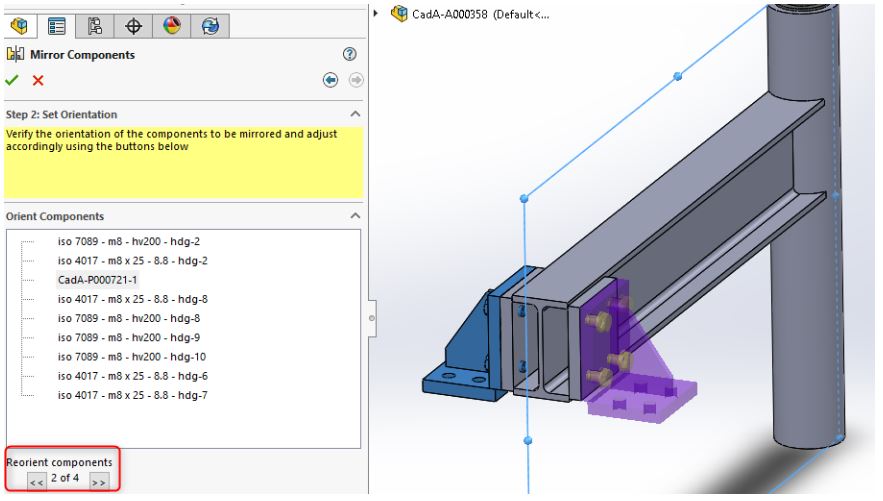
A couple of examples of what happens, when reorient components is used, are shown below.
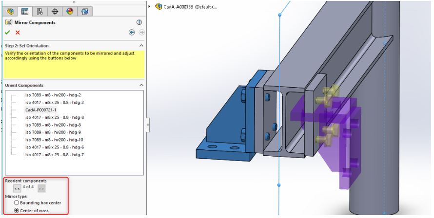
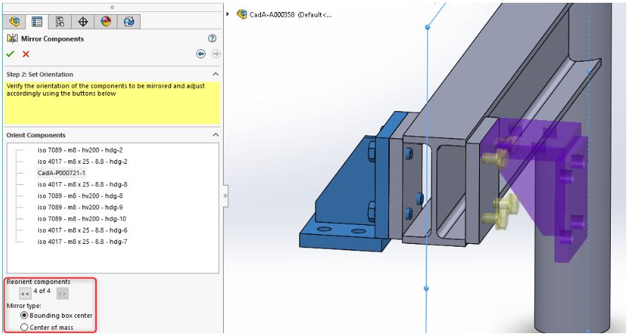
Also the difference between the Bounding box center and Center of mass is shown to illustrate Mirror type section.
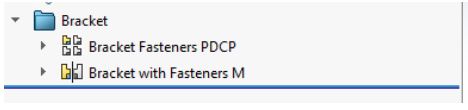
Top tip: It’s strongly recommended to rename the Mirror features, use a Folder to group them, or even better – both!
This is a simple and stable way without inducing problems in the PDM etc. Also, be advised that no opposite hand is needed.
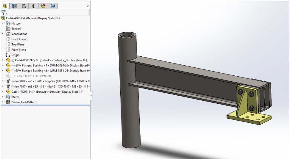
Mirroring in the case of an opposite hand version of a part
When using part mirroring in the assembly, one may run into a tricky situation where a part is clearly non-symmetric and an opposite hand version of it needs to be created. In the following example the yellow part will play that role.
Use Opposite Hand Mirror:
In the next chapters you’ll find two options:
Option A – Create new derived configuration in existing files
Option B – Create New Files
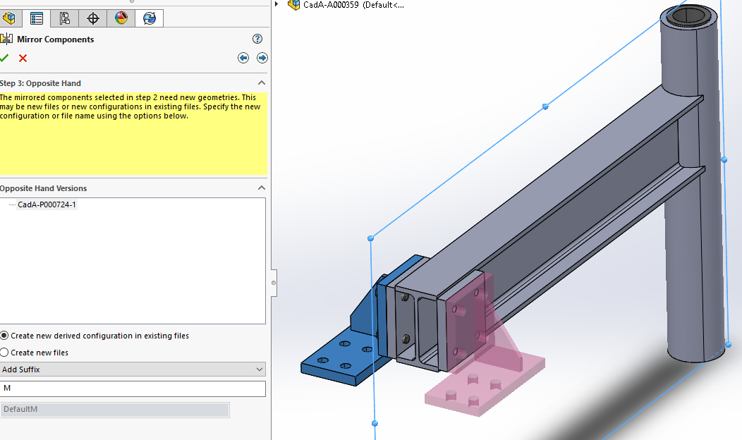
Option A – Create new derived configuration in existing files
This is a useful and quick way of doing things when the Mirror side is described in the drawing as “1 pc as shown in the drawing and 1 pc to be made as a mirror”. This is only suitable in some cases in project-based engineering. Keep in mind that this is the most dangerous way of approaching things as it leaves a lot of room for (mis)interpretation to other departments down the line.
This will not work if you have small or large series of fabrication and/or supply chain management.
A better and almost “bulletproof” way of doing this would be to just make two drawing files on top of one part file such as:
CadA-P000715.sldprt
CadA-P000715.slddrw
CadA-P000715M.slddrw (this can be a copied drawing file with a changed configuration in drawings views with minor fixes to the drawing)
For this approach, use mirroring as follows:
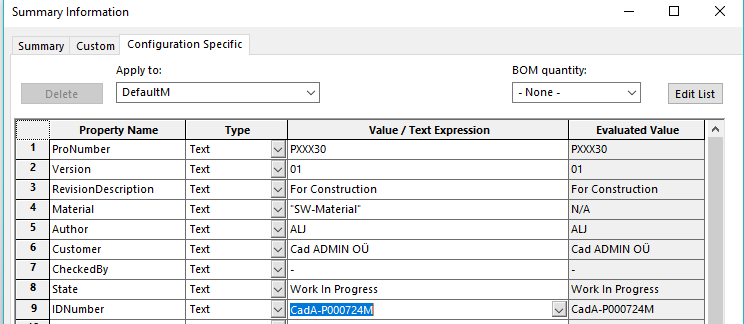
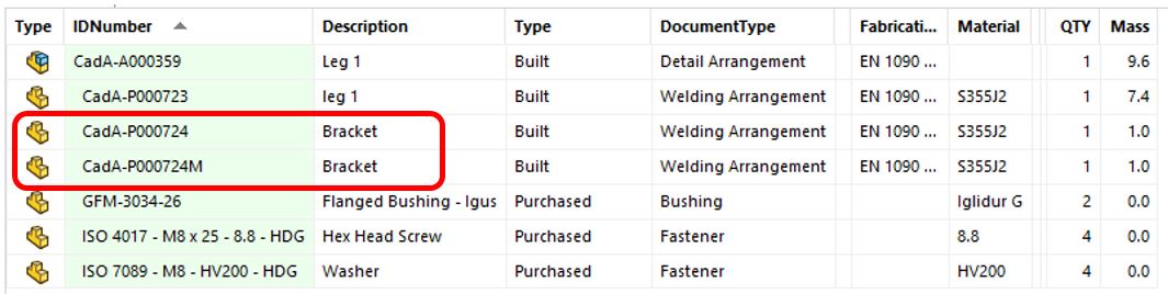
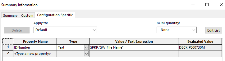
In this case the IDNumber in file properties for the mirror configuration must be also modified to show the correct ID in BOM.
When the PDM is set up so that all the configurations are always updated and the IDNumber is “greyed out” from user by default, then the IDNumber must be manually updated in the File Properties.
The same goes for the Description (Example: Bracket M) as otherwise both configurations would be updated.
Whether IDNumbers and Descriptions should be updated in all configurations or not is a topic for another time.
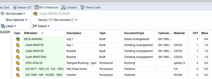
BOM view:
Overall using configuration mirror is the most stable way to go. This way there are no big issues with data cards and so on. Some manual workarounds must be done such as modifying the file properties, but this is a minor issue.
There is another minor issue in that this creates a derived configuration. It would be more logical for it to be a same level configuration. Should this be the need, the users must manually delete the derived configuration and resolve the mirror feature in the created “M” configuration. This is essential when using a PDM system other than the SW PDM. The treatment of derived configurations may differ a lot!
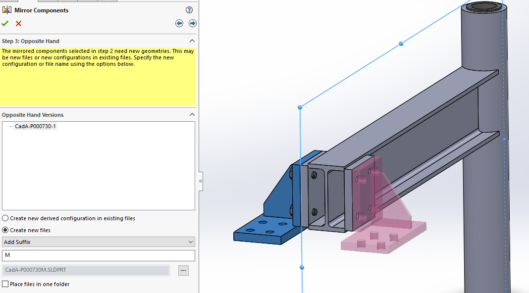
Option B – Create New Files
When you are a PDM user, remember that it’s unable to correctly assign a serial number when a mirrored part is saved as a separate part. Therefore it’s advised to use the suffix “M”. It may be renamed later, but that would mean having to change the references manually, which is a huge pain in the #¤%.
A good workaround or even a recommended practice is described in Part One.
NB! Keep in mind that when creating a mirror with a suffix, then manual editing of the file names is required whenever someone copies the main assembly tree with a copy tree command!
So choosing the option to save the mirror as a part will require a lot of work from the user through file properties as typically some fields in the PDM are greyed out (and often with good reason).
For this approach, it’s best to use mirroring as shown in part one.
Even if you choose Custom, you cannot give it a sequence number in the PDM.
Typically under Save as, you will have the option to generate a serial with a right click, but not here!
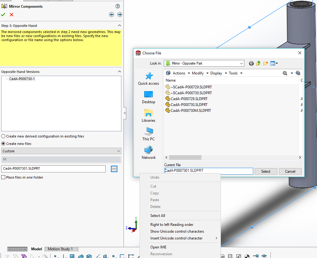
Custom Properties should only be used if you want the exact same properties as used in the base part. As there is no real way to change the IDNumber and Description – a question arises – as to what is the purpose of this, as in reality, different things must be identified differently.
Thus the following options are suggested for mirroring parts with cut list properties.
If it’s a single body, then cut list properties might not be needed.
If it’s a sheet metal part, then cut list properties should be deselected and sheet metal with unlocked properties should be selected.
Unlocked properties is a feature that should be available for custom properties and cut list properties but as of today, it isn’t.
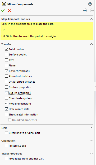
Some extra information about the other options is shown here, especially for sheet metal.
A mirrored part is initially empty of custom properties.
Therefore, make check-in (keep checked out) after mirroring. In most cases, this will fill most of the data card, but sometimes it doesn’t work well and a manual update of the properties is required.
Then simply add the IDNumber – text – $PRP:”SW-File Name” to ensure automatic filling.
And after checking everything, you get BOM:
Hopefully, this made things clearer when it comes to both SOLIDWORKS mirroring and mirroring in the SOLIDWORKS PDM.
We’ll continue this article to bring you part three as soon as possible.
Feel free to start a discussion below.